
Serving the Great Lakes Region -MI, OH, IN
|
|
Drilling Services
LFI recognizes that unique types of drilling projects require differing expertise. We specialize in installing wind turbine foundations, power and telecommunication foundations, drilled shafts for bridges, parking structures, and retention systems, as well as industrial and commercial building foundations.
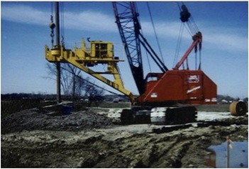
We have the capacity to drill diameters up to 21' and to a depth of 200 feet, straight or bell botttomed shafts, cased or uncased. We possess our own fleet of drill rigs, cranes, water truck & equipment, casings, augers, bellers, semitrucks, trailers, & lowboys which allows us to provide quick mobilization of equipment & accelerated start times for projects with varying sizes, complexities, and ground conditions.
Types of excavation include:
Dry Shaft Caissons
Wet Shaft Caissons
Rock Coring
Dry Shaft Construction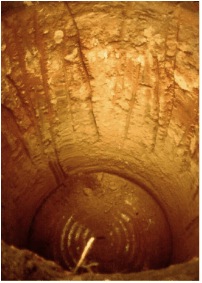
What is a Dry Shaft?
A shaft excavation that can be excavated to its designed depth without the need for slurry or casing. When Is a Dry Shaft Used? The dry construction method is used at sites where the ground water level and soil and rock conditions are suitable to permit construction of the shaft in a relatively dry excavation. and where the sides and bottom of the shaft may be visually inspected by the Engineer prior to placing the concrete. The dry method is by far the least expensive method for drilled shaft construction. |
Wet Shaft Construction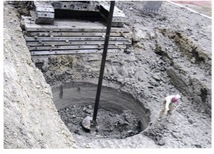
What is a Wet Shaft?
Often called the "slurry-method", wet shaft construction is when a slurry or water is used to keep the hole stable for the entire depth of the shaft. When is a Wet Shaft Used?
|
Wet Shaft Construction Process
Unlike the dry construction method, in this situation the water table may be above the shaft tip elevation or the geology consists of unstable or "caving" soils. Think of trying to dig a hole at the beach or lake near the water's edge. The hole stays open until you reach or get just below the water table or waterline. Then what happens? It collapses.
Well the same goes for drilled shafts excavated below the water table or in unstable soils. During the drilling of the hole, a slurry is introduced that "stabilizes" the sides of the hole or casing is installed and prevents the soils from collapsing into the hole.
Upon reaching the designed shaft tip elevation, the hole is cleaned, then the rebar cage placed.
Unlike the dry shaft method, the concrete is being placed "under the water" and therefore a tremie is lowered into the hole and the concrete placed through the tremie, which is carefully removed a little at a time to avoid "breaching" the concrete.
Types of Wet Shaft Construction
The Static Process
|
The Circulation Process
|
Drilling with Slurry
Slurry is the fluid introduced into the excavation to assist in maintaining hole stability. Generally, three basic types of "slurries", Mineral, Polymer and Water, are employed in drilled shaft construction.
What Does the Slurry Do?
In some instances, though not recommended, a blended slurry, consisting of mineral and polymer slurries is employed.
What Does the Slurry Do?
- Maintains a Stable Borehole Prior to Concreting
- Maintains High Effective Stresses in the Soil while the Hole is Open (Retard Softening or Loosening)
- Facilitates Removal of Cuttings in "Circulation Drilling"
In some instances, though not recommended, a blended slurry, consisting of mineral and polymer slurries is employed.
What Does it Mean When a Shaft is "Cased"?
The casing method is often used either when shown on the plans or at sites when construction methods are inadequate to prevent hole caving or excessive deformation. In this method the casing may be either placed in a predrilled hole or advanced through the ground by twisting, driving or vibration before being cleaned out. Casings and liners play an important role in the construction of drilled shafts, and special attention must be given to their selection and use.
Casings are tubes that are relatively strong, usually made of steel, and joined, if necessary, by welding. Liners, on the other hand, are light in weight and become a permanent part of the foundation. Liners may be made of sheet metal, plastic, or pressed fibers. While their use is much less frequent than that of casings, liners can become important in some situations.
Common situations where casing is used are:
- In generally dry soils or rocks that are stable when they are cut but which will slough soon afterwards. In such a case the borehole is drilled, and casing (a simple steel pipe) is quickly set to prevent sloughing.
- When there is a clean sand below the water table underlain by a layer of impermeable limestone or low permeability clay into which the drilled shaft will penetrate. In this case, since the overlying sand is water bearing, it is necessary to seal the bottom of the casing into the underlying rock/soil to prevent flow of water and caving of soils into the borehole.
